UART Protocol
UART framing, baud-rate generation, oversampling and VHDL implementation points.
What is UART?
UART (Universal Asynchronous Receiver/Transmitter) is an asynchronous serial protocol: unlike SPI and I2C, there is no shared clock between transmitter and receiver. Synchronization is achieved by a predefined communication rate called the baud rate (bits per second).
Key characteristics:
- Asynchronous: no shared clock
- Full-duplex: TX and RX are independent lines
- Point-to-point: 2 devices only (no multi-slave bus)
- Baud rate: both sides must be configured to the same rate
UART Signals
| Signal | Description |
|---|---|
| TX | Transmit - data sent |
| RX | Receive - data received |
| GND | Common ground (required) |
At rest, the TX line is high (logic '1', called "mark").
UART Frame
A standard UART frame (8N1 - 8 data bits, no parity, 1 stop bit):
- Start bit: low level for 1 bit period - signals the beginning of the frame
- Data bits: 5 to 9 bits, LSB first (standard convention)
- Parity bit (optional): even, odd, or none
- Stop bit(s): high level for 1 or 2 bit periods - end of frame
Baud Rate and Clock Divider
The baud rate determines bit duration: T_bit = 1 / baud_rate
| Baud Rate | T_bit |
|---|---|
| 9600 bps | 104.2 µs |
| 115200 bps | 8.68 µs |
| 1 Mbps | 1 µs |
To generate the baud rate from a system clock, calculate a divider:
DIVIDER = SYS_CLK / BAUD_RATE
Example: 100 MHz / 115200 ≈ 868
VHDL Implementation
The UART transmitter uses a state machine with 4 phases: IDLE, START, DATA and STOP. A clock divider (CLK_SYS / BAUD_RATE) generates the timing for each bit. Data is sent LSB first, following the standard.
Available UART exercises:
- UART 8N1 Transmitter - Implement a UART TX with baud-rate generator and FSM.
- Simple Full-Duplex UART - Implement 8N1 TX and RX with mid-bit sampling.
- UART top-level assembly - Wire a complete UART top-level from provided components.
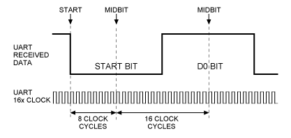
UART Receiver - 16x Oversampling
The receiver must synchronize on the Start bit, then sample each data bit at the center of its period to maximize noise immunity.
The classic technique is 16x oversampling: the frequency divider generates 16 ticks per bit period. The receiver:
- Waits for the falling edge of the Start bit
- Waits 8 ticks (half period) to position at the center of the Start bit
- Verifies the line is still low (validates the Start bit)
- Every 16 ticks, samples a data bit
constant c_DIV16 : positive := g_CLK_HZ / (g_BAUD * 16);Key Points
- Same baud rate on both sides: a difference of more than 3-5% causes decoding errors
- Logic inversion: RS-232 UART uses ±12 V levels. A MAX232 or adapter is required for 3.3 V or 5 V interfaces
- No error detection: except with the optional parity bit - higher-level protocols (e.g., Modbus) add checksums
- Idle level: the TX line must be high at rest. A disconnected TX will be seen as a continuous data stream
Advantages and Disadvantages
| Advantages | Disadvantages |
|---|---|
| Simple, only 2 wires | Point-to-point only |
| No shared clock | Identical baud rate required on both sides |
| Widely supported | No native error detection |
| Longer distances (RS-232/485) | No multi-master capability |
📝 Test your knowledge - Chapter quiz