Complete Vitis tutorial: control LEDs over UART | FPGAPourTous
Summary
Complete Vitis tutorial: control LEDs over UART
Create a platform, standalone domain and Cortex-A53 application that controls the four ZCU104 user LEDs from a serial terminal.
Tutorial objective
This tutorial builds a complete Vitis project. The application is bare-metal: it runs directly on the Cortex-A53 without a complete operating system. Vitis calls this execution environment standalone.
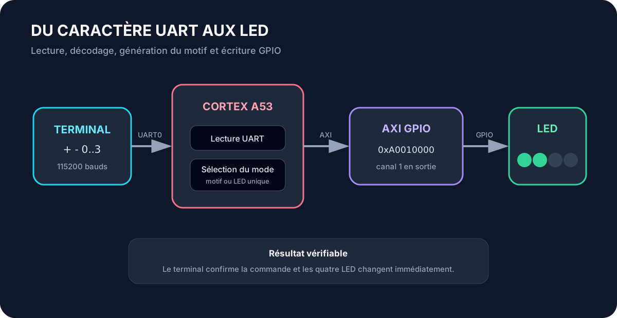
At the end, a character sent at 115200 baud through the UART protocol controls the four ZCU104 user LEDs. + and - move the center of a brightness pattern. Digits 0 through 3 toggle one LED.
Required hardware and files
The tutorial targets a ZCU104 and psu_cortexa53_0 in the Zynq UltraScale+ MPSoC. It uses Vitis 2022.2, a standalone domain and fpt_zcu104_base.xsa.
The XSA hardware archive is required and must be available before starting. Another XSA may use different peripheral names, addresses or LED routing.
Element
Value used in this tutorial
Board
ZCU104
Connection
USB JTAG and USB UART
Boot mode
JTAG
SW6 position
ON, ON, ON, ON
Processor
psu_cortexa53_0
Operating system
standalone
Hardware description
fpt_zcu104_base.xsa
Serial rate
115200 baud
LED GPIO
XPAR_FPT_LED_BANK_DEVICE_ID
Address in the supplied BSP
0xA0010000
The program uses the generated BSP symbol rather than copying the address.
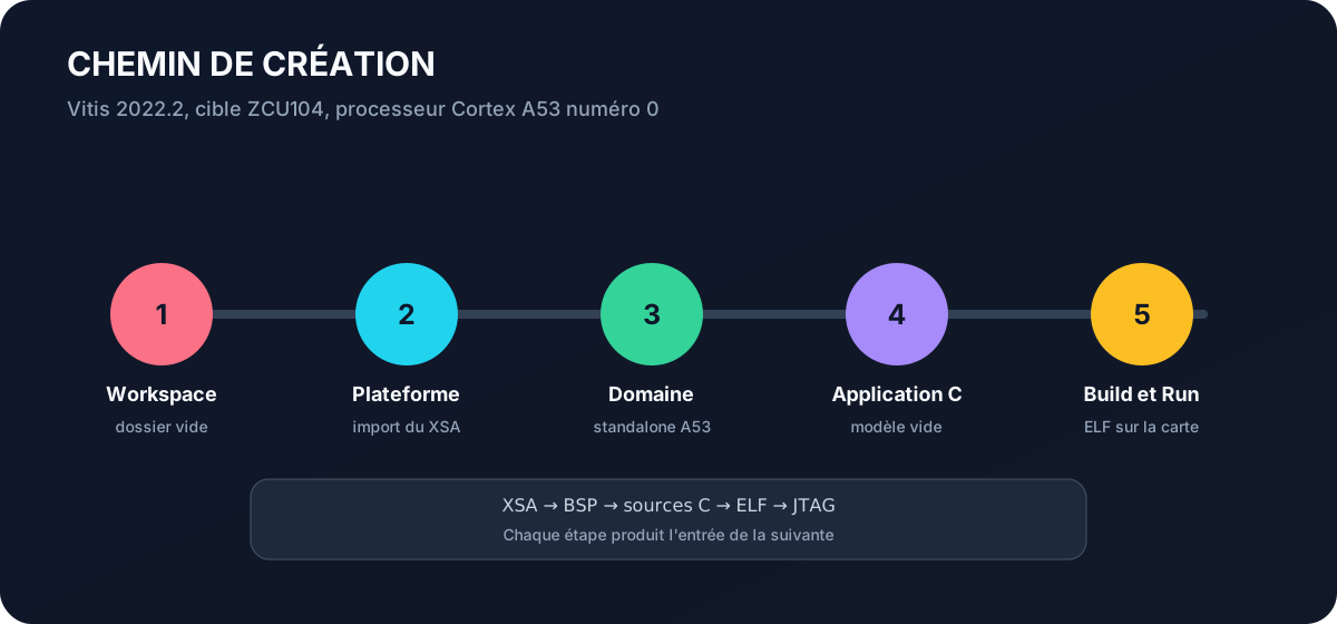
Step 1: create the workspace
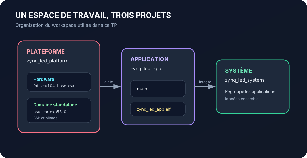
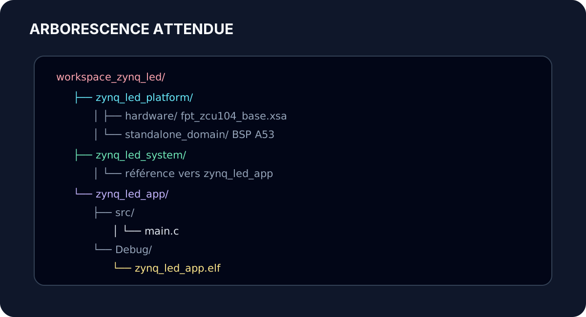
Start Vitis 2022.2 and select an empty workspace directory. A workspace is the folder where Vitis stores the platform, application, system project and local settings.
C:\zynq-workspaces\workspace_zynq_led
Step 2: create the platform
Open the menu next to Create New and select Platform Project. Name the platform zynq_led_platform.
Select Create a new platform from hardware (XSA) and choose the fpt_zcu104_base.xsa file prepared for the tutorial.
Field
Value
Operating system
standalone
Processor
psu_cortexa53_0
Boot components
Create the FSBL for the target processor
Click Finish to start generation. Vitis then produces the platform, standalone domain, BSP and boot components from the previous choices.
The platform must show a hardware description and a domain attached to Cortex-A53 core 0.
Step 3: create the application and system
Open Create New and select Application Project. Select zynq_led_platform.
Field
Value
Application project name
zynq_led_app
System project
Create New
System project name
zynq_led_system
Processor
psu_cortexa53_0
Domain
Platform standalone domain
Template
Empty Application (C)
Click Finish.
Step 4: inspect the BSP
Open xparameters.h from the BSP and search for FPT_LED_BANK.
Also confirm that STDIN_BASEADDRESS exists. It is 0xFF000000 in this platform and identifies the PS UART used by the terminal.
Step 5: add the program
Right-click src in zynq_led_app and create main.c. Paste the following program. Its names describe each value directly and its state handling is deterministic.
init_platform() calls the preparation code defined in the project's platform.c file. Its exact content depends on the processor and platform. It may handle caches or a 16550 UART, but it does not replace initialize_led_output(), which explicitly initializes the AXI GPIO used by this tutorial.
cleanup_platform() runs the shutdown operations defined by platform.c. In this program, it is called only when GPIO initialization fails. The while (1) loop does not end during normal operation, so code placed after that loop could not run.
XUartPs_IsReceiveData tests for input without blocking the loop. XGpio_Initialize binds user_leds to the instance generated in the BSP. XGpio_SetDataDirection configures channel 1 as outputs.
DISPLAY_HOLD preserves a binary LED image. DISPLAY_FADE uses 32-phase software PWM. Each mask selects the phases during which one LED is on.
Step 7: build the project
Save main.c. Right-click zynq_led_app and select Build Project, or use the hammer icon with the Debug configuration.
The console should report a successful build and display ELF section sizes.
text data bss dec hex filename... ... ... ... ... zynq_led_app.elfBuild Finished
If XPAR_FPT_LED_BANK_DEVICE_ID is missing, the XSA does not expose the expected GPIO instance or the BSP is stale. Inspect xparameters.h instead of guessing a replacement.
If a saved correction does not affect the result, run Build Project explicitly. Vitis 2022.2 does not rebuild on every save.
Step 8: prepare the ZCU104
Power the board off. Connect USB JTAG and USB UART. Set all four SW6 switches to ON for JTAG boot, then power the board on.
Identify the serial port assigned to the PS UART.
Step 9: create a run configuration
Right-click zynq_led_app, then select Run As and Run Configurations.
Create a Single Application Debug configuration. In Target Setup, confirm that a bitstream is selected and Program FPGA or Program Device is enabled.
Click Run. Vitis initializes the target, programs the PL and loads zynq_led_app.elf.
Step 10: open the serial terminal
Open Window, Show View, Xilinx, then Vitis Serial Terminal. Create a connection, select the ZCU104 port and set 115200 baud.
Zynq LED console readyUse +, -, or a digit from 0 to 3
Step 11: validate behavior
Command
Expected result
+
Move the pattern center to the next LED
-
Move the pattern center to the previous LED
0 to 3
Toggle the selected LED
x
Print Unsupported command
The center remains inside the 0 to 3 range at both endpoints.
Step 12: diagnosis
If the terminal is empty, check the selected port, baud rate, JTAG mode and run configuration.
If the terminal works but LEDs do not, check the generated GPIO identifier, bitstream programming, GPIO channel and the 0xA0010000 address in the supplied BSP.
If the pattern flickers, adjust only the wait_count limit. This changes software PWM speed without changing command behavior.
Engineering exercises
Replace software PWM with a hardware timer.
Add a c command that clears all LEDs.
Report the current mode when ? is received.
Measure refresh frequency with an ILA.
Split the program into console.c, led_output.c and main.c.
Key points
A Vitis application depends on a platform, domain, application project and system project. The XSA supplies hardware. The BSP supplies symbols and drivers. The build produces an ELF executable. The run configuration programs the target and loads that executable through JTAG. PWM, or pulse-width modulation, controls average LED brightness by rapidly varying the proportion of on time.