Vivado Hardware Platform
Build a Zynq platform in IP Integrator, connect IP, assign addresses and export the hardware to Vitis.
The role of Vivado
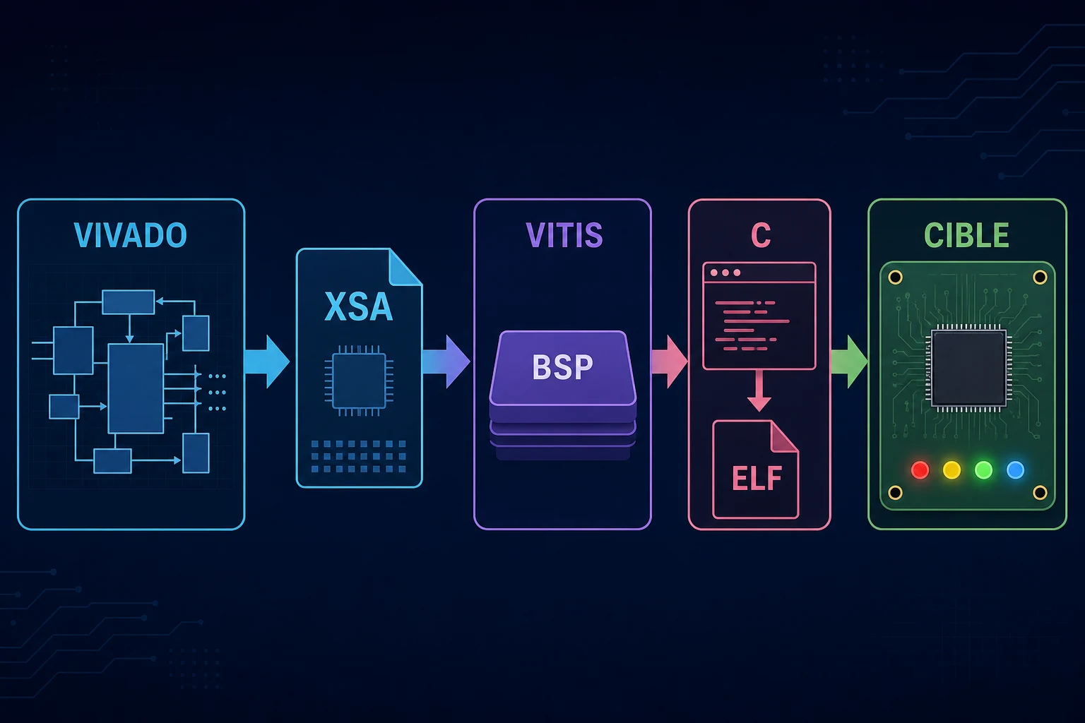
The engineer uses Vivado to build the hardware part of a Zynq system. The project describes the device, Processing System, programmable logic, clocks, resets, addresses and board pins.
IP Integrator provides a graphical view called a Block Design. An IP is a reusable hardware block, such as a processor, GPIO controller or custom accelerator. In this view, the engineer adds blocks and connects their interfaces. The Block Design does not replace the VHDL or Verilog contained in custom blocks.
This chapter presents a complete flow. You create the project, run Tcl commands, add and configure IP, insert an HDL block, create hierarchy, mark debug nets, configure the PS, assign addresses and generate the final wrapper.
Create the project
Select the exact board or device. This choice controls the available resources, I/O banks and Processing System configuration.
A ZCU104 project uses a Zynq UltraScale+ MPSoC. A ZedBoard or ZC702 project uses Zynq-7000. Port names and parameters differ between these families.
A board file supplies useful presets. You must still verify the actual pinout, clocks and interfaces on the board.
Add and configure the Processing System
Add the PS block from the IP catalog. Vivado then offers block automation. When you run it, the tool applies a board preset and creates the basic connections.
The PS configuration includes the following items.
- DDR memory.
- UART, SPI, I2C, Ethernet and SD peripherals.
- MIO or EMIO assignments.
- Clocks sent to the PL.
- AXI ports between PS and PL.
- Interrupts coming from the PL.
Always review the preset. An enabled interface will not work if its pins or clock are wrong.
Add an AXI GPIO
To make the steps concrete, this course builds a small system with two AXI GPIO blocks. The first drives the board LEDs. The second reads the buttons. AXI GPIO has an AXI-Lite interface for registers and one or two GPIO channels for external signals.
The processor is the AXI-Lite transaction master. It reads and writes GPIO registers. AXI GPIO is the slave. Its PL outputs connect to LEDs and its inputs connect to buttons.
When you run connection automation, Vivado can insert the following required blocks.
| Block | Purpose |
|---|---|
| AXI SmartConnect or AXI Interconnect | Connects masters and slaves |
| Processor System Reset | Creates synchronous resets for a clock domain |
| AXI GPIO | Provides registers and GPIO signals |
| Concat | Groups interrupts into a vector |
Review automatic connections. Check master and slave directions, clock domains, reset polarity and port widths.
Add an HDL block
In IP Integrator, you can add a reference to an HDL module without packaging it as an IP first. This action creates an instance of the module in the Block Design. The HDL code needs a clearly defined top-level entity or module. Its ports then appear on the graphical block.
This method is suitable for small local logic. A packaged IP is better when the block must be reused, configured with parameters or shared across projects.
A block crossing clock domains needs an explicit CDC method. A valid graphical connection does not guarantee safe clock domain crossing.
Manage addresses
Every memory-mapped AXI slave receives an address range. Address Editor displays the masters, slaves and related segments.
Software does not invent these addresses. The engineer assigns them in Address Editor. Vivado records them in the exported platform, and BSP generation then produces the matching constants in xparameters.h.
#define XPAR_FPT_LED_BANK_BASEADDR 0xA0010000U
#define XPAR_FPT_LED_BANK_HIGHADDR 0xA001FFFFUExact values depend on the project. Use generated symbols instead of copying an address from another design.
Validate the Block Design
Validation detects structural errors. It can report an unconnected interface, a missing clock or an invalid address range.
Validation does not prove that the system meets its requirements. It does not verify the behavior of custom IP. It does not replace simulation, static timing analysis or board testing.
A useful review checks the following items.
- Every clock has a known frequency.
- Every reset is synchronized in its clock domain.
- Address ranges do not overlap.
- Interrupts reach the correct controller.
- External ports have XDC constraints.
- Automatic AXI width and protocol conversions are understood.
Generate and export the platform
Generate the HDL wrapper for the Block Design. This top-level module exposes the external ports. The engineer then starts synthesis and implementation. Vivado executes these steps and produces the bitstream, which is the binary configuration loaded into the programmable logic.
Hardware export creates an XSA archive. It contains the hardware description, addresses and processor configuration seen by Vitis. It can also include the bitstream.
When an address, IP or interrupt changes in Vivado, regenerate the XSA and update the Vitis platform. Otherwise, software may compile against an old hardware description.
Automate with Tcl
Vivado exposes its objects and commands through Tcl. The examples use Tcl to create projects, add blocks, find objects and rebuild a platform.
The main benefit is reproducibility. A versioned script can rebuild the Block Design and expose important parameters. Generated Vivado files should not replace a controlled description of the system.
Official references
The Vivado Design Suite User and Reference Guides catalog links the Block Design, platform creation and IP packaging guides for the relevant Vivado release.
Key points
Vivado is the tool used to describe the hardware platform. In IP Integrator, the engineer assembles the PS, AXI IP and HDL blocks. The engineer assigns addresses in Address Editor. The validation command searches for structural errors. The XSA file then transfers the hardware description to Vitis.
Test your knowledge - Chapter quiz